Beam characteristics and geometry
A medical linear accelerator (linac) generates and shapes the beam, depending on photon mode or electron mode.
- The electron gun and accelerating waveguide are common to both modes, where the electrons are generated by a heated cathode, and then accelerated down a waveguide to near relativistic energies.
- x-ray target (PHOTON MODE): the electrons are directed into a thick tungsten target where they undergo rapid deceleration and produce bremsstrahlung (broad spectrum of x-ray photons). In electron mode, the x-ray target is retracted so as to convert the electrons into x-rays
- primary collimator (BOTH) = safety boundary that defines the maximum possible field size
- scattering foil (ELECTRON MODE) = spreads out the narrow pencil-thin beam of electrons in a uniform lateral profile. This is the functional analog to the flattening filter in photon mode
- flattening filter (PHOTON MODE) = the x-ray spectrum is a forward peaked x-ray beam and so the flattening filter attenuates the central axis more than the periphery, evening out the dose profile to produce a flat field
- leaving the flattening filer in the electron mode would scatter and attenuate the electrons too much
- ion chamber (BOTH) = measures the dose rate and beam symmetry in real time
- secondary collimator (jaws) (BOTH)
- in photon mode, they move in orthogonal pairs to shape the field precisely. One pair controls the in-plane (Y1 and Y2) dimension, the other controls the cross-plane (X1 and X2) dimension
- custom blocks can also be used that are patient specific inserts made of lead. These have largely been replaced by MLC
- multi-leaf collimator (MLC) = 160-120 tungsten leaves (2.5 mm to 1 cm width) driven by individual motors
- in electron mode, the jaws are opened to a fixed aperture
- electron applicator (ELECTRON MODE) = attaches to the treatment head and extends close to the patient’s skin to minimize the air gap
Additional beam modifiers
- wedges = modify dose distribution laterally
- can be physical (wedge shaped attenuator) or dynamic (uses sweeping jaw Y to shape the beam)
- compensators = beam modifying devices used to even out the skin surface contour to create dose homogeneity
- bolus =tissue equivalent material (wax, rubber or thermoplastic gel) placed directly on the patient skin to compensate for missing tissue and improve dose coverage to the skin
Photon beam
Beam energies used in external beam therapy =
- superficial (30 kVp to 8 kVp)
- othovoltage (100 kVp to 300 kVp)
- megavoltage (Co-60 to 25 MV)
Depth of dose maximum
- depends on beam energy and beam field size
- 6 MV = 1.5 cm
- 10 MV = 2.5 cm
- 15 MV = 3 cm
- 6 MV flattening filter free (6 MV-FFF) = 1.2 cm
- 10 MV-FFF = 2 cm
Percentage Depth Dose (PDD) = ratio of dose at a specified depth to dose at
- measured at an SDD set up
- , shape of curve, and gradient of curve increases with energy
Tissue phantom ratio (TPR) = ratio of dose at a specified depth to dose at reference depth
- at SAD set-up, since SDD changes with each depth
- depends on energy, depth and field size
- When reference depth is then it is called Tissue maximum ratio (TMR)
Relative Dose factor (RDF) = ratio of dose for the specified field size to dose at reference field size (10 x 10 cm)
- two components
- collimator factor
- phantom factor
Wedge factor (WF) = ratio of dose with wedge to dose without wedge (open field)
Transmission factor (TF) = ratio of dose with an attenuator to dose without
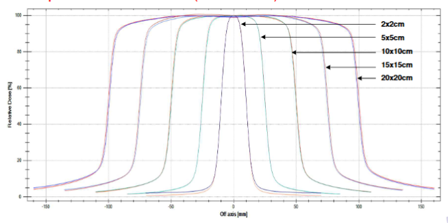
Beam profile
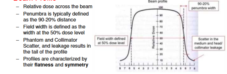
open field profiles (flattened)
wedge profiles
